

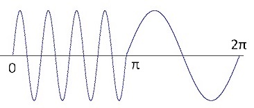
Frequency shift keying is used to transmit digital data for instance in amateur radio technology. The digital information is transmitted by shifting the frequency of the carrier signal. The frequency for a logical 1 is usually higher than the frequency for a logical 0. A 1, 0 sequence looks like:

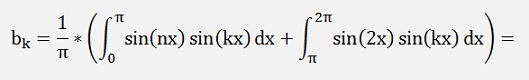
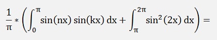
For the bk components:
There are 4 situations:
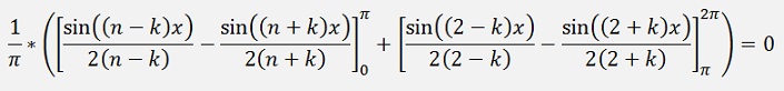
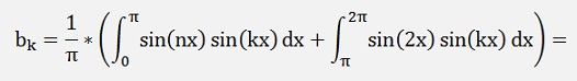
If k ≠ n and k ≠ 2
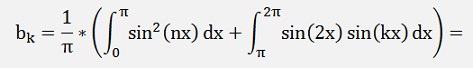
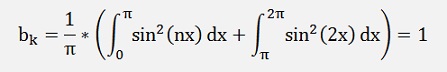
If k = n and k ≠ 2
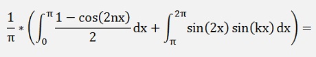

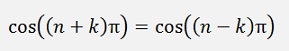
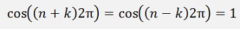
If k = n and k = 2
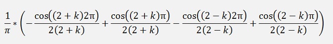
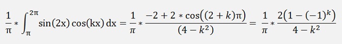
If k ≠ n and k = 2
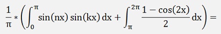

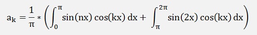
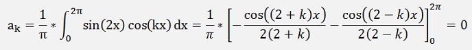
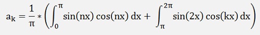
For the ak components:
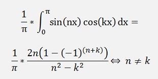
We first take a look onto the first part:
If k ≠ n
(See ASK signal)
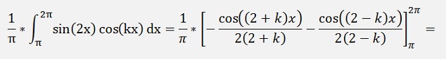
Now the second part:
If k ≠ n
as
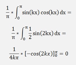
If n = k
n ≠ k and k ≠ 2


In code with ak as real parts and bk as imaginary parts:
private void Fsk(double peak, int n)
{
int
j;
c[0].real = 0;
for (j = 1; j < 500; j++)
{
c[2].imag = peak / 2.0;
if (n == 2)
{
else
{
c[0].real = 0;
for (j = 1; j < 500; j++)
{
c[j].imag
= 0;
if ((n + j) % 2 == 0)
{
if ((j != 2) && ((j) % 2 != 0))
}if ((n + j) % 2 == 0)
c[j].real
= 0;
else{
if
(j != n)
}c[j].real
= peak / Math.PI
* (2.0 * (double)n
/ ((double)n * (double)n
- (double)j * (double)j));
elsec[j].real
= 0;
if ((j != 2) && ((j) % 2 != 0))
c[j].real
= c[j].real - peak / Math.PI
* (4.0 / (4.0 - (double)j
* (double)j));
c[2].imag = peak / 2.0;
if (n == 2)
{
c[n].imag
= peak;
c[n].real = 0;
}c[n].real = 0;
else
{
c[n].imag
= peak / 2.0;
}
}That creates for n=4 a spectrum like:
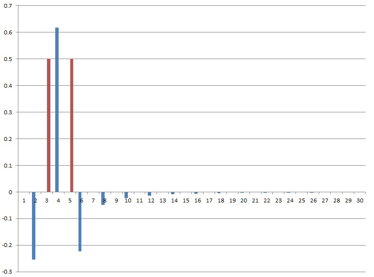
The blue bars are the real elements and red the imaginary parts.
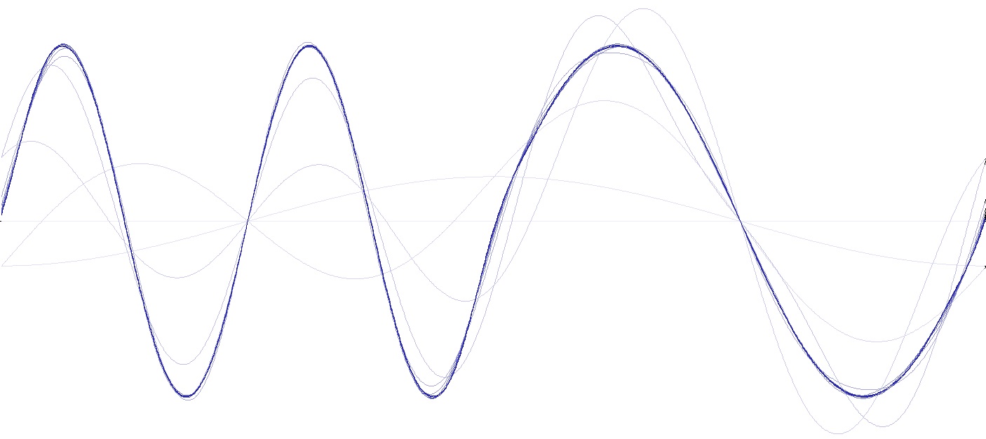
And with all the harmonics put together, we get the signal shape. The brightest line is the base frequency. The next darker is the base frequency plus the first harmonic, then comes the same plus the next harmonic … and so on. The more harmonics are included, the closer the shape approximates the origin shape quite soon

C# Demo Project Fourier signals