The PWM (pulse width modulated) signal is used to control the power supplied to electrical devices. I had to develop a PWM power amplifier for a 12 V 20 A supply once. Quite an interesting, and transistor consuming, task. Was funny to see how quick a FET transistor burns through if it becomes overheated

See Pulse-width_modulation wiki
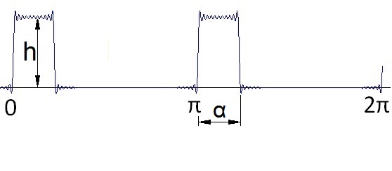
My signal shape looks like:

For the ak components:


If k is even

If k is odd

and the bk components:


If k is even

If k is odd

Implemented in a function that would look like:
private void Pwm(double peak, double alpha)
{
int
j;
c[0].real = peak * alpha / 3.141596;
for (j = 1; j < 500; j++)
{
}c[0].real = peak * alpha / 3.141596;
for (j = 1; j < 500; j++)
{
if
(j % 2 == 0)
{
else
{
}{
c[j].real
= 2.0 *peak / Math.PI
/ j * Math.Sin(j
*
alpha);
c[j].imag = 2.0 * peak / Math.PI / j * (1.0 -Math.Cos(j * alpha));
}c[j].imag = 2.0 * peak / Math.PI / j * (1.0 -Math.Cos(j * alpha));
else
{
c[j].real
= 0;
c[j].imag = 0;
}c[j].imag = 0;
with ak as real parts and bk as imaginary parts.
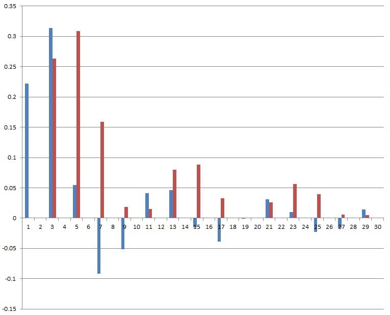
And that calculates this spectrum for the first 30 harmonics (with a pulse width of 40°) :

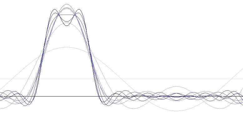
And if all the harmonics are put together, we get the origin signal shape.

The brightest line is the base frequency. The next darker is the base frequency plus the first harmonic, then comes the same plus the next harmonic … and so on. The more harmonics are included, the closer the shape approximates the origin shape.
C# Demo Project Fourier signals

